Electrical Resistance (ER) Monitoring |
View PDF version 
|
Introduction
The electrical resistance (ER) technique is an "on-line" method of monitoring the rate of corrosion and the extent of total metal loss for any metallic equipment or structure. The ER technique measures the effects of both the electrochemical and the mechanical components of corrosion such as erosion or cavitation. It is the only on-line, instrumented technique applicable to virtually all types of corrosive environments.
Although universally applicable, the ER method is uniquely suited to corrosive environments having either poor or non-continuous electrolytes such as vapors, gases, soils, "wet" hydro-carbons, and nonaqueous liquids. Examples of situations where the ER approach is useful are:
- Oil/gas production and transmission systems
- Refinery/petrochemical process streams
- External surfaces of buried pipelines
- Feedwater systems
- Flue gas stacks
- Architectural structures
An ER monitoring system consists of an instrument connected to a probe. The instrument may be permanently installed to provide continuous information, or may be portable to gather periodic data from a number of locations. The probe is equipped with a sensing element having a composition similar to that of the process equipment of interest. |
| |
Principles of Operation
The electrical resistance of a metal or alloy element is given by:

where:
L = Element length
A = Cross sectional area
r = Specific resistance
Reduction (metal loss) in the element's cross section due to corrosion will be accompanied by a proportionate increase in the element's electrical resistance.
Practical measurement is achieved using ER probes equipped with an element that is freely "exposed" to the corrosive fluid, and a "reference" element sealed within the probe body. Measurement of the resistance ratio of the exposed to protected element is made as shown in Figure 1. |
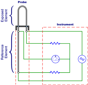
Figure 1. Probe / Instrument
|
Since temperature changes effect the resistance of both the exposed and protected element equally, measuring the resistance ratio minimizes the influence of changes in the ambient temperature. Therefore, any net change in the resistance ratio is solely attributable to metal loss from the exposed element once temperature equilibrium is established.
Additionally, all standard Metal Samples ER probes incorporate a protected "check element" which is used to indicate probe integrity. The value of the check element is indicated as the Check Reading on most ER meters. Because it is sealed within the probe, the check element's reading should remain unchanged over time.
The Check Reading is typically set around 80% of full scale on most ER probes (represented as a value of 800 out of 1000 on a conventional ER meter). The exact value will be printed on the ER probe's data tag. While slight variations in the Check Reading are to be expected, a significant change in value or a continual trend away from the stated value may indicate that the probe element is leaking. In this case the probe should be removed for inspection at the earliest convenience and any data from the probe should be taken with scrutiny until its condition can be verified.
Measurement of the ER probe may either be taken periodically using a portable instrument, or on a continuous basis using a permanently installed unit. In either case, Metal Samples Corrosion Monitoring Systems ER instruments will produce a linearized signal which is proportional to the metal loss of the exposed element. The rate of change in the instrument output is a measure of the corrosion rate. Continuously monitored data is usually transmitted to a computer/data-logger and treated to give direct corrosion rate information. Manual graphing techniques are usually used to derive corrosion rate from periodically obtained data as illustrated in Figure 2. |
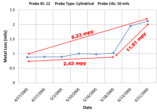
Figure 2. Graph plotting measurement versus time to derive corrosion rate.
|
| |
ER Sensing Elements
Sensing elements are available in a variety of geometric configurations, thicknesses, and alloy materials. Available element types are shown in Figure 3. |
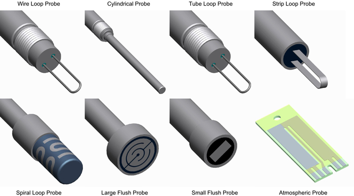
Figure 3. ER Sensing Elements
|
Wire loop elements are the most common element available. This type of element has high sensitivity and low susceptibility to system noise, making it a good choice for most monitoring installations. Wire loops are generally glass-sealed into an endcap which is then welded to the probe body. The glass seal, which is chemically inert in most environments and has a good pressure and temperature rating, makes a good choice for most applications. Alloys commonly glass sealed are Carbon Steel, AISI 304 and 316 stainless steels. Where glass may be susceptible to corrosion problems, Teflon®-sealed elements are also available. Probes with wire loop elements are normally equipped with a flow deflector (or velocity shield) to protect the element from floating debris in the piping system.
Tube loop elements are recommended where high sensitivity is required to rapidly detect low corrosion rates. Tube loop elements are manufactured from a small bore, hollow tube formed into the above loop configuration. Carbon Steel is the alloy most commonly used. Tube loops sealed into the probe by a Teflon® pressure seal are also available. Probes using the tubular loop element can be equipped with a flow deflector to minimize possible distortion in fast flowing systems.
Strip loop elements are similar to the wire and tube loop configurations. The strip loop is a flat element formed in a loop geometry. The strip loop may be glass or epoxy sealed into the endcap depending on the required application. The strip loop is a very sensitive element. Strip loops are very fragile and should only be considered for very low flow applications.
Cylindrical elements are manufactured by welding a reference tube inside of a tube element. This element has an all welded construction which is then welded to the probe body. Because of this element's all welded construction, exotic alloy elements can be produced relatively easily. This probe is ideally suited to harsh environments including high velocity and high temperature systems, or anywhere a glass-sealed element is not an option.
Spiral loop elements consist of a thin strip of metal formed on an inert base. The element is particularly rugged and ideal for high-flow regimens. Its comparatively high resistance produces a high signal-to-noise ratio, which makes the element very sensitive.
Flush mount elements are designed to be mounted flush with the vessel wall. This element is very effective at simulating the true corrosion condition along the interior surfaces of the vessel wall. Being flush, this element is not prone to damage in high velocity systems and can be used in pipeline systems that are subject to pigging operations.
Surface strip elements (for atmospheric probes) are thin rectangular elements with a comparatively large surface area to allow more representative results in non-homogeneous corrosive environments. Strip elements are commonly used in underground probes to monitor the effectiveness of cathodic protection currents applied to the external surfaces of buried structures. |
| |
Corrosion Rate Calculation
When measuring the ER probe, the instrument produces a linearized signal (S) that is proportional to the exposed element's total metal loss (M). The true numerical value being a function of the element thickness and geometry. In calculating metal loss (M), these geometric and dimensional factors are incorporated into the "probe life" (P) (see Table 1), and the metal loss is given by:

Metal loss is conventionally expressed in mils (0.001 inches), as is element thickness.
Corrosion rate (C) is derived by:
T being the lapse time in days between instrument readings S1 and S2.
Table 1 lists element types, thicknesses, probe life, and identification numbers. For temperature and pressure ratings see respective probe data sheets. When selecting an element type for a given application, the key parameters (apart from the fundamental constraints of temperature and pressure) in obtaining optimum results are response time and required probe life. Element thickness, geometry, and anticipated corrosion rate determine both response time and probe life. Response time, defined as the minimum time in which a measurable change takes place, governs the speed with which useful results can be obtained. Probe life, or the time required for the effective thickness of the exposed element to be consumed, governs the probe replacement schedule. |
| |
| Element Type |
Thickness |
Probe Life |
Element ID |
| Wire loop |
40 mil
80 mil |
10 mil
20 mil |
WR40
WR80 |
| Tube loop |
4 mil
8 mil |
2 mil
4 mil |
TU04
TU08 |
| Strip loop |
5 mil
10 mil |
1.25 mil
2.5 mil |
SL05
SL10 |
| Cylindrical |
10 mil
20 mil
50 mil |
5 mil
10 mil
25 mil |
CT10
CT20
CT50 |
| Spiral loop |
10 mil
20 mil |
5 mil
10 mil |
SP10
SP20 |
| Flush (small) |
4 mil
8 mil
20 mil |
2 mil
4 mil
10 mil |
FS04
FS08
FS20 |
| Flush (large) |
5 mil
10 mil
20 mil
40 mil |
2.5 mil
5 mil
10 mil
20 mil |
FL05
FL10
FL20
FL40 |
| Surface Strip |
10 mil
20 mil
40 mil |
5 mil
10 mil
20 mil |
SS10
SS20
SS40 |
Table 1. Probe Life and Element ID
|
| Since probe life and response time are directly proportional, element selection is a compromise between data frequency and probe replacement frequency. The graphical relationship between corrosion rate, probe life, and response time for all elements normally available from Metal Samples Corrosion Monitoring Systems is shown in Figure 4. |
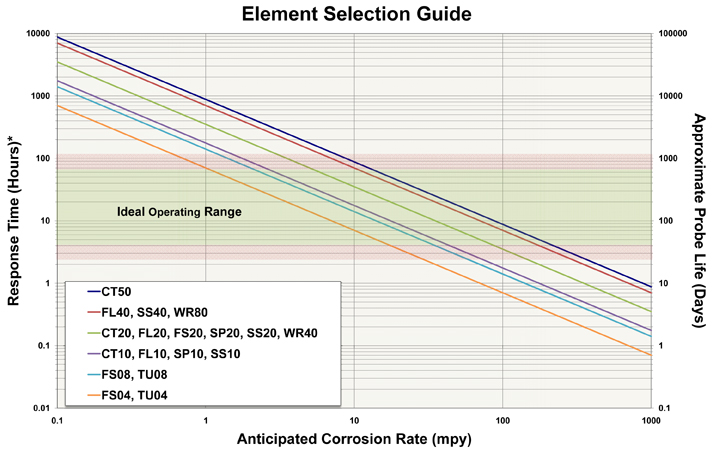
* Response Time is the minimum time required for a 0.4% (4 probe division) change.
Figure 4. Element Selection Guide
|
| |
Probe Features
Metal Samples Corrosion Monitoring Systems ER probes are available in a variety of configurations and are discussed in detail in later pages of this catalog. The brief summary provided here, gives only a broad overview of probe construction.
The standard material of construction for all Metal Samples Corrosion Monitoring Systems probe bodies is AISI 316L stainless steel which conforms with NACE standard MR0175 for sour service conditions. Other materials may be available for extremely aggressive environments. Contact our sales department to discuss alternative options.
The primary pressure sealing mechanism for Metal Samples Corrosion Monitoring Systems ER probes is the element seal, which varies with the precise element specification. However, all Metal Samples Corrosion Monitoring Systems process probes incorporate, at the instrument end, a glass-sealed, pressure-rated, electrical connector. The connector provides a fail-safe seal should leakage develop in the element seal.
The simplest of all probe body configurations is the fixed version, shown in Figure 5. Typically equipped with an NPT pipe plug or flange connection, the fixed probe is screwed or bolted into place. Probe installation or removal can only be performed during shut-down, unless the probe is installed in a side-stream which may be isolated and depressurized. The frequency of shut-down should be a factor in the selection of probe life criteria.
|
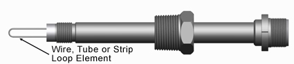
Figure 5. Fixed Probe
|
Retractable probes are supplied with a 1-inch FNPT packing gland to allow probe insertion and removal through a customer-supplied ball valve, in systems with pressures not exceeding 2000 psi. A safety frame of rods and plates may be attached to the probe to prevent "backing out" in systems with high vibration. Metal Samples Corrosion Monitoring Systems requires the Easy Tool for probe insertion or retraction in systems with pressure over 150 pounds.
Retractable probes find wide applications in refinery and petrochemical industries. A typical probe is shown in Figure 6. |
| |
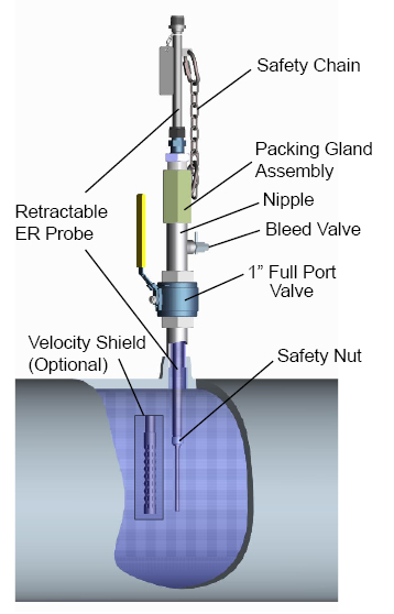
Figure 6. Retractable Probe
|
| Retrievable probes are employed in process systems operating at pressures up to 3600 psi. These probes must be used in conjunction with specially designed fittings, retrieval tools and service valves, all of which are described in the High Pressure Access Systems section. The retrievable design is the industry standard for oil production systems. A typical installation is shown in Figure 7. |
| |
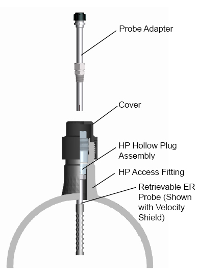
Figure 7. Retrievable Probe
|
| Teflon® is a registered trademark of DuPont. |