|
|
Linear Polarization Resistance (LPR) Monitoring |
View PDF version 
|
Introduction
The electrochemical technique, commonly referred to as Linear Polarization Resistance, is the only corrosion monitoring method that allows corrosion rates to be measured directly, in real time. Although limited to electrolytically conducting liquids, the response time and data quality of this technique make it clearly superior, where applicable, to all other forms of corrosion monitoring.
Polarization resistance is particularly useful as a method to rapidly identify corrosion upsets and initiate remedial action, thereby prolonging plant life and minimizing unscheduled downtime. The technique is utilized to maximum effect, when installed as a continuous monitoring system.
This technique has been used successfully for over thirty years, in almost all types of water-based, corrosive environments. Some of the more common applications are:
- Cooling water systems
- Secondary recovery system
- Potable water treatment and distribution systems
- Amine sweetening
- Waste water treatment systems
- Pickling and mineral extraction processes
- Pulp and paper manufacturing
- Hydrocarbon production with free water
|
| |
Principles of Measurement
When a metal/alloy electrode is immersed in an electrolytically conducting liquid of sufficient oxidizing power, it will corrode by an electrochemical mechanism. This process involves two, simultaneous, complementary reactions.
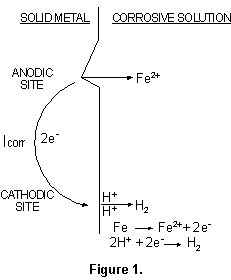
At anodic sites, metal will pass from the solid surface into the adjacent solution and, in so doing, leave a surplus of electrons at the metal surface. The excess electrons will flow to nearby sites, designated cathodic sites, at which they will be consumed by oxidizing species from the corrosive liquid. A simple example, of iron dissolving in acidic solution, is illustrated in Figure 1.
|
|
The corrosion current (ICORR), generated by the flow of
electrons from anodic to cathodic sites, could be used to compute the corrosion rate by
the application of a modified version of Faraday's Law:

where:
C = Corrosion rate in "mils per year" (MPY)
E = Equivalent weight of the corroding metal (g)
A = Area of corroding electrode (cm2)
d = Density of corroding metal (g/cm3)
However, anodic and cathodic sites continually shift position, and they exist within a
continuously conductive surface, making direct measurement of ICORR impossible.
Small, externally-imposed, potential shifts (E) will produce measurable current flow (I)
at the corroding electrode. The behavior of the externally imposed current is governed, as
is that of ICORR, by the degree of difficulty with which the anodic and
cathodic corrosion processes take place. The greater the difficulty, the smaller the value
of ICORR, and the smaller the value of I for a given potential shift. In fact,
at small values of E, I is directly proportional to ICORR, and hence to the
corrosion rate. This relationship is embodied in the theoretically derived Stern-Geary
equation:

The numbers ba and bc are empirical rate constants, the Tafel constants, so the
relationship can be more simply expressed as:
ICORR = I/E x constant (3)
The value E/I is known as the Polarization Resistance. In principle it is most easily
measured by placing a second electrode (auxiliary) in the liquid, and connecting it to the
corroding electrode (test) through an external power supply. This is illustrated in Figure
2.
|
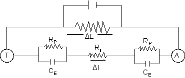
Figure 2.
|
RP = Polarization Resistance
RS= Solution Resistance
CE= Electrode Capacitance
The applied potential, in this simple type of two-electrode measurement, is required to
over-come the solution resistance as well as the polarization resistance of the corrosion
reactions. Consequently, the polarization resistance will be overestimated by I(Rs), and
the corrosion rate will be underestimated to an extent given by:

where:
CM = Measured corrosion rate
CA = True corrosion rate
Metal Samples Corrosion Monitoring Systems has largely overcome the problem of solution resistance error by using a proprietary, three-electrode measurement (the PAIR™ technique). This uses separate circuits for the measurement of I and E. The circuit in which the E measurement is made has an extremely high input impedance, consequently solution resistance has negligible effect on the value of potential shift applied to the test electrode. The basis of the PAIR™ technique is illustrated in Figure 3.
|
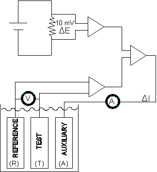
Figure 3.
|
When a measurement is made, the PAIR™ instrument will initially null any residual potential difference between the reference electrode (R) and the test electrode (T). After which, current will flow from the auxiliary electrode (A) onto the test electrode. The flow of current, between the auxiliary electrode and the test electrode, will increase until the test electrode potential is shifted 10 mV with respect to the reference electrode. The current (I) required to sustain the 10 mV potential shift is proportional to the corrosion rate of the test electrode.
The polarizing voltage of 10 mV, that is used in PAIR™ instrumentation, has been chosen as being well within the limits for which the linear relationship between ICORR and E/I holds. Additionally, the value is sufficiently small as to cause no significant, or permanent disruption of the corrosion process, so that subsequent measurements remain valid.
The instrument reading is given directly as "mils per year." The constant of proportionality, incorporated into the PAIR™ instrumentation, is an empirical number determined by comparison of E/I values with weight loss measurements for several hundred alloy/environment systems. This ensures a sound, experimental basis for instrument calibration.
Individual corrosion rate measurements will show a decay characteristic, due to capacitative effects, that exist, to some degree, at all corroding electrode surfaces. This decay pattern is illustrated in Figure 4.
|
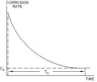
Figure 4.
|
The true value of corrosion rate, is the equilibrium value (Ce), that is established after a time interval Tc. This time lag will vary, depending on the specific characteristics of the metal/environment system, between approximately 30 seconds and several hours. Since the decay characteristic is asymptotic, even systems with extreme "capacitative inertia" will closely approach equilibrium within 15-20 minutes; so that most practical measurements can be concluded within a 0.5-20 minute duration. A variable "time cycle" feature is incorporated into automatic PAIR™ instrumentation to accommodate this capacitative time-lag.
|
| |
Probe / Element Selection
Three-electrode probes are available with a triangular or linear-pin configuration, and in a concentric-ring, flush arrangement. When solution resistances reach extremely high values (10kΩ/cm), the choice of electrode configuration becomes important. This is due to the spreading effect produced by high resistivity on the current field between the test and auxiliary electrode that, at some point, will allow current to impinge on the reference electrode and displace its potential. The effect is illustrated in Figure 5.
|
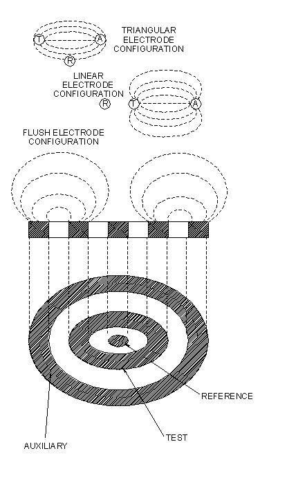
Figure 5.
|
Clearly, a linear-pin electrode configuration is less effected by "current spread" than is a triangular array. Concentric ring, flush, electrode configurations are essentially immune from "current spread" effects, due to mutual interference of current fields on opposite quadrants of the disc. As an approximate guide, a triangular electrode array can be used in solutions having specific resistances up to 10kΩ/cm, and the linear configuration up to 50kΩ/cm. In principle, the flush array will operate successfully as long as the environment offers some electrolytic conductance, however, 500kΩ/cm is a good guide to practical working limits. Electrode configuration is, therefore, of primary importance in selecting a probe type for a given application.
Most other criteria for probe selection relate to the physical characteristics of the system, such as temperature and pressure ratings, and whether probe insertion/removal must be undertaken without system depressurization. Metal Samples Corrosion Monitoring Systems offers a wide variety of probe body styles, addressing these various needs. The simplest probe body style is the fixed length version, an example of which is shown in Figure 6.
|
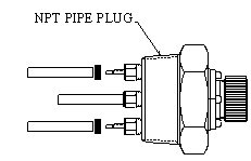
Figure 6.
|
Typically equipped with an NPT bushing, the fixed PAIR™ probe is screwed into place. Probe installation requires system depressurization, unless an isolatable side-stream device is employed. Versions of this probe with 1" NPT, 1½" NPT, and 2" NPT entry bushing are available, with a maximum operating pressure of 3600 psi. An adjustable length version (shown in Figure 7) is also available with a movable entry bushing that will operate up to 1500 psi.
|

Figure 7.
|
Retractable probes, supplied with a 1" FNPT packing gland are available. Used in conjunction with a 1'', full-port, ball-valve these probes can be inserted and removed without system depressurization at pressure up to 2000 psi.
Retractable probes can be supplied with a safety frame that prevents probe "backout" in high vibration systems, and aids the insertion/removal process at the high end of the pressure operating range (above 250 psi).
For insertion/removal at high operating pressures, Metal Samples Corrosion Monitoring Systems offers the retrievable probe. This style probe can be inserted and removed, without system depressurization, at operating pressures up to 3600 psi. To accomplish high-pressure retrieval, the probe is used in conjunction with a special range of fittings, plugs, tools, and valves that are discussed in the High Pressure Access Fittings section of this catalog. The retrievable installation, a standard for the oil and gas production industries, is illustrated in Figure 8.
|
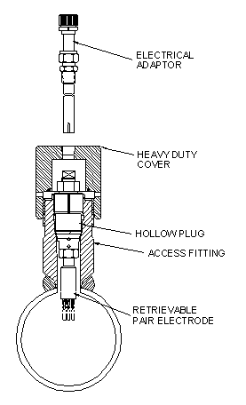
Figure 8.
|
All probe body configurations discussed are for industrial use, and are constructed of AISI 316L stainless steel. As such, they meet NACE material standard MR0175 for sour service use. Additionally, all industrial quality PAIR™ probes have a glass-sealed, electrical connector that has an operating pressure rating of 6000 psi, to provide a "fail-safe" seal in the unlikely event that the primary electrode seals fail.
Metal Samples Corrosion Monitoring Systems also offers a range of laboratory PAIR™ probes and cells, side-stream devices, custom test-loops for laboratory investigation.
|
| |
Instrumentation
Metal Samples Corrosion Monitoring Systems offers a wide range of PAIR™ instrumentation to suit almost any customer application. Instrument products offered include:
- Battery-powered, portable units (with or without data storage)
- Single channel, automatic units
- Multi-channel units
- 4-20 mA transmitters for distributed data acquisition
- Multi-function instruments
T being the lapse time in days between instrument readings S1 and S2.
Table 1 lists element types, thicknesses, probe life, and identification numbers. For temperature and pressure ratings see respective probe data sheets. When selecting an element type for a given application, the key parameters (apart from the fundamental constraints of temperature and pressure) in obtaining optimum results are response time and required probe life. Element thickness, geometry, and anticipated corrosion rate determine both response time and probe life. Response time, defined as the minimum time in which a measurable change takes place, governs the speed with which useful results can be obtained. Probe life, or the time required for the effective thickness of the exposed element to be consumed, governs the probe replacement schedule.
|
| |
Replacement Electrodes
Replacement of electrode elements by the user is a unique feature of Metal Samples Corrosion Monitoring Systems probes. Field changes are quickly made without special tools or techniques.
Comparisons of metals and alloys under operating conditions can be conveniently and economically accomplished. Substitution of identical fresh electrodes of the same material for badly corroded or contaminated elements is a practical approach to evaluating changes in process conditions or inhibitor effectiveness from the same starting conditions of surface quality and dimensions.
The use of the replacement electrodes for weight loss measurements is an attractive possibility for many experimenters. The fact that both polarization and gravimetric measuring methods are made on the same test specimen eliminates several variables from comparative evaluations.
Surface areas of the different metals and alloys are adjusted to compensate for variations in chemical activity and density. Thus a direct mpy meter readout is obtained in each case for the electrodes listed.
Electrodes are sold as a single unit. In most cases, the electrodes used will be of the same metal alloy; however, some users may wish to vary the electrodes. Each electrode is enclosed in an inhibited paper package along with a gasket. Viton® gaskets are standard and supplied unless another material is specifically requested.
Electrodes can be provided from many alloys with material supplied either by Metal Samples Corrosion Monitoring Systems or by the customer. Electrodes from the customer's weld metal can be machined by Metal Samples Corrosion Monitoring Systems. Inquiries for electrodes of special alloys are encouraged.
Viton® is a registered trademark of DuPont Dow Elastomers. |
| |
|
|
|

