With a non-flanged access fitting:
Top-of-the-line Monitoring: L = (H + PW) - 2.5"
One half of the coupon extends into the pipe and the process environment. The other half is positioned in the access fitting body cavity and may be used to monitor the formation of gas pockets.
Middle-of-the-line Monitoring: L = (H + ½OD) - (2.5" + ½CL)
The coupon is centered so that ½ of the coupon is positioned on either side of the pipe’s centerline.
Bottom-of-the-line Monitoring: L = (H + OD) - (2.75" + PW + CL)
The coupon is positioned approximately ¼" off the bottom of the line.
With a flanged access fitting:
Top-of-the-line Monitoring: L = (H + FG + MH + PW) - 2.5"
Middle-of-the-line Monitoring: L = (H + FG + MH + ½OD) - (2.5" + ½CL)
Bottom-of-the-line Monitoring: L = (H + FG + MH + OD) - (2.75" + PW + CL)
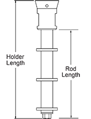
Where:
L = Coupon holder length
H = Height of the access fitting body without a thread protector (MH = 5.5"/14 cm, HP = 5.25"/13.3 cm)
PW = Pipe wall thickness
OD = Outside diameter of the pipe
CL = Effective length of the coupon (the portion of the coupon that is actually exposed to the process environment)
For a 3" coupon, CL = 1.625" (4.13 cm)
For a 6" coupon, CL = 4.750" (12.07 cm)
FG = Gap between mating flange faces
MH = Mating flange height from face to top of pipe
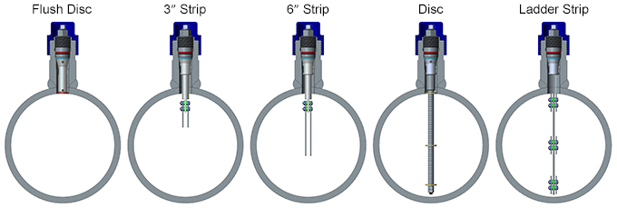
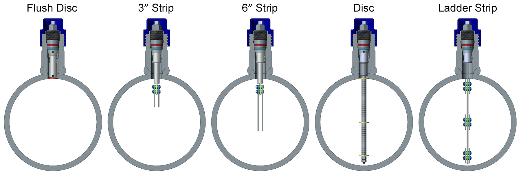
Disc Coupon Holders
Disc coupon holders are used with flush disc type coupons for measurement in either flush or non-intrusive configurations. They are available as fixed length or adjustable assemblies. These coupon holders offer the following advantages over strip coupon holders:
- They can be mounted flush with the pipe wall so that process effects occurring at the pipe wall are closely simulated.
- Holders properly sized to the flush position prevent coupon interference with pigging operations.
- Orientation of coupons to process flow is not required.
|

