Corrosion Coupons & Weight Loss Analysis |
View PDF version 
|
Introduction
The simplest, and longest-established, method of estimating corrosion losses in plant and equipment is weight loss analysis. A weighed sample (coupon) of the metal or alloy under consideration is introduced into the process, and later removed after a reasonable time interval. The coupon is then cleaned of all corrosion product and is reweighed. The weight loss is converted to a corrosion rate (CR) or metal loss (ML), as follows:
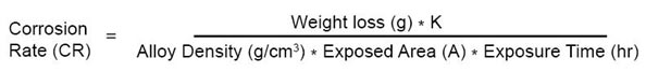
The constant can be varied to calculate the corrosion rate in various units:
| Desired Corrosion Rate Unit (CR) |
Area Unit (A) |
K-Factor |
| mils/year (mpy) |
in2 |
5.34 x 10⁵ |
| mils/year (mpy) |
cm2 |
3.45 x 10⁶ |
| millimeters/year (mmy) |
cm2 |
8.76 x 10⁴ |
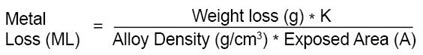
| Desired Metal Loss Unit (ML) |
Area Unit (A) |
K-Factor |
| mils |
in2 |
61.02 |
| mils |
cm2 |
393.7 |
| millimeters |
cm2 |
10.0 |
The technique requires no complex equipment or procedures, merely an appropriately shaped coupon, a carrier for the coupon (coupon holder), and a reliable means of removing corrosion product without disruption of the metal substrate. Weight loss measurement is still the most widely used means of determining corrosion loss, despite being the oldest method currently in use.
- Weight loss determination has a number of attractive features that account for its sustained popularity:
- Simple - No sophisticated instrumentation is required to obtain a result.
- Direct - A direct measurement is obtained, with no theoretical assumptions or approximations.
- Versatile - It is applicable to all corrosive environments, and gives information on all forms of corrosion.
The method is commonly used as a calibration standard for other means of corrosion monitoring, such as Linear Polarization and Electrical Resistance. In instances where slow response and averaged data are acceptable, weight loss monitoring is the preferred technique.
|
| |
Coupon Preparation and Cleaning
The choice of technique for initial preparation of the coupon surface, and for cleaning the coupon after use, is critical in obtaining useful data. Both the relevance and reproducibility of weight loss data are highly sensitive to the inherent suitability of these techniques, and to the care with which they are executed.
Surface finishing methods vary across a broad range for specific applications. Blasting with glass bead, sand, or other aggregate can provide an acceptable finish for some applications. Sanding with abrasive belts, or surface or double disc grinding with abrasive stones also provides an excellent surface for evaluation.
Cleaning of specimens before weighing and exposure is critical to remove any contaminants that could affect test results.
Reference should be made to NACE Recommended Practice RP-0775 and ASTM G-1 & G-4 for further detail on surface finishing and cleaning of weight-loss coupons.
|
| |
Coupon Position and Orientation
Irrespective of the degree of care exercised in the surface preparation of coupons, many uncontrollable factors (e.g. microstructural defects) can reduce the accuracy of weight loss determinations. Therefore, using duplicate (Figure 1) or multi-replicate (Figure 2) coupon samples is considered good practice.
Coupon orientation must be consistent in order to make different data sets comparable. Generally, an orientation parallel to the process flow is preferable since this more nearly reflects the true condition experienced by the vessel wall (Figure 1). Metal Samples Corrosion Monitoring Systems' MH™ coupon holders have an automatic flow alignment feature. All other holders are marked on the top side with flow direction for manual alignment.
|
Figure 1. Preferred Flow Direction
|
Positioning is another critical factor in obtaining relevant information. For example, a multi-phase product may produce layered flow, giving rise to corrosion rates that vary with depth in the process stream. Such situations can be monitored with a ladder-strip coupon holder (Figure 2).
|
Figure 2. Ladder Strip Coupon Holder
|
Possibly the most common issue in coupon positioning arises from the fact that a true representation of the corrosion experienced by the pipe/vessel can only be established when the weight loss coupon is in the plane of the vessel/pipe wall. Only in this position can the coupon experience the same flow regime as the pipe surface being monitored. In response to this situation, the use of flush-disc coupons has become widespread (Figure 3).
|
Figure 3. Flush Disc Coupon Holder in High Pressure Access Fitting
|
The general issue of coupon orientation and positioning in relation to flow regime, plant geometry, and process fluid, is complex, and tends to be specific to each application. However, the most common coupon configurations have been discussed above.
|
| |
Coupon Holders
Specific design of coupon holders incorporates two basic factors:
- Number, style, and configuration of coupons
- System entry method
|
| |
| Fixed (Pipe Plug) Coupon Holders
The simplest system entry design for coupon holders is the fixed or pipe plug coupon holder (Figure 4). This type of coupon holder is normally offered on a ¾", 1", or 2" NPT pipe-plug. The size of the plug to be used is the limiting factor as to the coupon configuration that can be used. These coupon holders are usually constructed in AISI 316L stainless steel, have a pressure rating of 3000 psi, and a temperature rating of 450°F/232°C. This design of coupon holder is recommended for use in a by-pass loop which can be isolated, or in systems having frequent and regular shut-down, since system depressurization is required during insertion and removal.
|
| |
Figure 4. Fixed (Pipe Plug) Coupon Holder
|
| |
| Retractable Coupon Holders
A design that is commonly used in the refining and petrochemical industry is the retractable type coupon holder as shown in Figure 5. This coupon holder design employs a packing gland that allows insertion and removal, through a ball-valve, without system depressurization. A safety cable and safety nut are also provided to prevent blowout. Retractable coupon holders can be used up to 1500 psi and 500°F (260°C), and are constructed of AISI 316L stainless steel. Normally, a 1" FNPT packing gland is used in conjunction with either a 1", or a 1½" full port ball valve, depending on the type of coupon configuration chosen. (See RT4000 sheet for more information.)
|
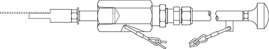
Figure 5. Retractable Coupon Holder
|
| |
| Retrievable Coupon Holders
The oil and gas production industry generally employs retrievable coupon holders that operate with high pressure access systems. This will allow insertion/removal under pressures up to 3600 psi. Metal Samples Corrosion Monitoring Systems supplies both generic (HP™) and proprietary (MH™) coupon holders. (See Coupon Holders for High Pressure Access Systems.)
The retrievable coupon holder is installed on to the solid plug. The assembly can then be inserted or removed from the system using a special service valve and retrieval tool.
Retrievable coupon holders are generally constructed in AISI 316L stainless steel to meet the requirements of NACE standard MR0175 for sour service use. These are available for all standard coupon configurations.
Retrievable, retractable, and pipe plug style coupon holders cover the needs of most industries and applications. However, the requirement for special coupon holder designs is significant, and Metal Samples Corrosion Monitoring Systems has the facility to design and build coupon holders to any customer-supplied specification. |
| |