Injection and Sampling systems are fundamental to corrosion control and process control programs. They are applicable to a large variety of processes in the petroleum, chemical, and water treatment industries. Injection systems are used to inject a wide range of chemicals into processes. Such chemicals include biocides, demulsifiers, corrosion inhibitors, oxygen scavengers, glycol and mono-ethylene glycol, dewaxers, methanol, odorizers, and product additives.
Injection systems may be as simple as using an open-ended tube that allows for even distribution of the injected chemical or as complex as using a head with a cap and core to obtain precise atomization of the chemical.
Sampling systems are used to take samples of the process fluid or medium. Such samples are then analyzed in the laboratory for inhibitor concentration levels, the presence of metal ions, oxygen levels, scale forming compounds, and a wide range of process parameters. Injection Systems
The art of chemical injection is a complex technology. Irrespective of the type of injection or injected fluid, several factors relative to the process system and the injection system must be considered. Principal factors are: Pressure Differential
This is the difference between the injection pump pressure and the process line or vessel pressure. Ideally the pressure differential should be 100 PSI (6.8 Bar). However, varied injection rates can be achieved by changing the pressure differential. Temperature
Temperature directly affects viscosity. Ideally the temperature of both the injected chemical and the line product should be about 70° F (21° C). Viscosity
This is the measure of a fluid's resistance to flow. The more viscous the fluid the smaller the spray angle. Spray Angle
Spray angle is affected by viscosity, spray distance, and pressure differential. Spray Coverage
This is the theoretical coverage area. Specific Gravity
The specific gravity of a liquid is the density ratio of the liquid to water. The flow rate of a liquid is affected by its specific gravity. Injection Rate
This is the amount of chemical to be injected within a specified time and is defined as Gallons Per Hour (GPH), Liters Per Day (LPD), etc. Injection Systems are available for injection rates varying from 0.1 GPH (0.38 liters/hr) to 65.7 GPH (250 liters/hr). Injection Point
The maximum fluid velocity is usually at the center of the line. Therefore, the most effective position for injection is generally at the center of the pipe in the direction of the product flow. If the line is to be pigged, the injection point may be flush with the pipe wall. This eliminates the need to remove the injection probe before pigging operations begin. On pipelines this means that injection is perpendicular to the product flow. Top of the line may be used if the injection is required to be oblique or horizontal to the product flow.
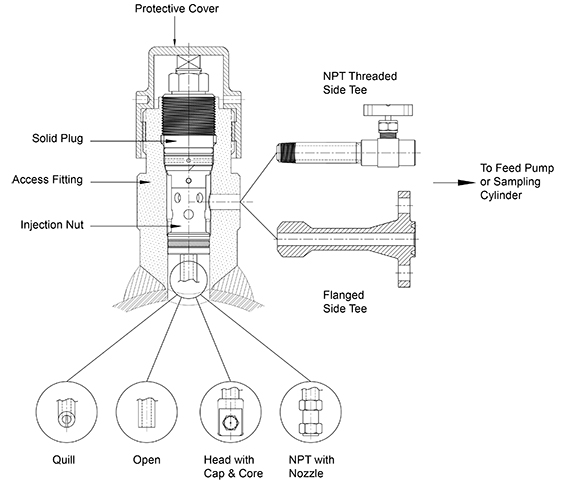
A typical Injection Assembly for use with High Pressure Access Systems is shown in Figure 1. A Sampling system uses the same components. The various components of the assembly are:
- An Access Fitting body with a side Tee through which the fluid transfer takes place. The Tee may be threaded or welded. Welded Tees are either flanged or buttweld nipples. Threaded Tees are based on an NPT tapped hole in the fitting body. The Tee size is rated according to the injection rate and viscosity of the injected chemical.
- A Solid Plug Assembly inside the fitting body is used to carry an injection nut that has the injection tube/nozzle assembly screwed into its base.
- An Injection/Sampling Nut is a multiple use device that replaces the nut on the end of the solid plug. It is used to direct the injected product to the injection tube or atomization device. An Injection Nut sizing chart is shown in Table 1.
- The Injection/Sampling Tube or Nozzle.
Options:
a. Quill is an open-ended tube cut at a 45° angle with a slot. It utilizes the turbulence created by its unique design to achieve distribution of the injected chemical into the product flow. Injection Tube Quills are clog proof and give extremely good dispersion of the inhibitor if the product flow is 15 ft. per second or greater. As with the Open Tube, injection rate must be controlled at the injection pump or shut-off valve.
b. Open is an open tube. The natural turbulence within the pipeline is used to insure even distribution. There is essentially no pressure differential experienced at the orifice, so it is necessary to control the injection rate at the injection pump or the shut-off valve.
c. NPT is similar to the Open Tube but is threaded at the dispersion end, thus allowing attachment of female nozzle assemblies. Injection may be perpendicular to the flow with the use of a straight nozzle or parallel to the flow with the use of a right angle nozzle.
d. Head with Caps, Cores, and Strainers are the various devices that, when attached to the dispersion end of the Injection Tube, permit atomization of the fluid as it is injected into the product line or vessel. The assemblies can be provided in complete units that contain caps, cores, and strainers. The head has female threads to match threads on the caps, cores, and strainers, so that these attachments can easily be replaced.
- Nipples are used with threaded Tee Access Fitting bodies and are the means of connecting the shut-off valve to the Access Fitting body.
- Shut-Off Valves are required to cut off the injection flow and maintain pressure integrity through the Tee when the Solid Plug Assembly is being removed or replaced. They are also used to control the injection flow rate. A Nipple and Shut-Off Valve sizing chart is given in Table 3.
- Check Valves are optional items that may be fitted either within the Injection Tube or in the inlet line to the Access Fitting Body Tee.
- The Injection or Feed Pump must be capable of generating sufficient injection line pressure to overcome the line operating pressure and thus create the required pressure differential across the atomizing nozzle or injection tube.
Materials of Construction
All components are manufactured from 316 SS as standard with the exception of seals and packing. These materials comply with the requirements of NACE Standard MR0175 Recommended Materials for sulfide stress cracking environments. Injection Tube Sizing
(Lengths are rounded down to the nearest 1/4, except for flush devices which are rounded down to the nearest 1/8".)
Center of Line Non-Flange Fitting
Open/Quill: (FH + PD/2) - (2.04 + N) = L
Head: (FH + PD/2) - (2.04 + N) = L
*NPT: (FH + PD/2) - (3.353 + N) = L
Center of Line Flange Fitting
Open/Quill: (FH + PD/2 + MF) - (2.04 + N) = L
Head: (FH + PD/2 + MF) - (2.04 + N) = L
*NPT: (FH + PD/2 + MF) - (3.353 + N) = L
Flush Non-Flange Access Fitting
Open/Quill: (FH + PW) - (2.04 + N) = L
Head: (FH + PW) - (2.04 + N) = L
*NPT: (FH + PW) - (3.353 + N) = L
Flush Flange Access Fitting
Open/Quill: (FH + PW + MF) - (2.04 + N) = L
Head: (FH + PW + MF) - (2.04 + N) = L
*NPT: (FH + PW + MF) - (3.353 + N) = L
FH = Access Fitting Height
PW = Pipe Wall Thickness
N = Injection Nut Length
L = Injection Tube Length
MF = Mating Flange Height
PD = Pipe Outer Diameter
IL = Insertion Length into Pipe or Vessel
*Length of tube is based on nozzle length of 1.313".
Nozzle is sold separately.
Ordering Information
A) Access Fitting Body height & Tee Size may be determined from the Access Fitting
product literature.
B) Injection Nut
C) Injection Tube Thread Size
Determine the Type.
Calculate the Injection Tube Length using the sizing formulas.
D) Nipple to match the Tee of the Access Fitting
Body
E) Shut-Off Valve to match the Tee of the Access Fitting
Body
F) Nozzle Type or Cap & Core Assembly (if applicable)
|